Search This Blog

Monday 27 April 2015

El sitgeti-AC and DC Connection cupboad

El Sitgeti-Connection point 2


Nothing special about this point, it is just a connection point were the upper part AC and DC lines are connected to the lower part AC and DC lines. Though I thought it still deserves a picture for the beauty of the integration of the cupboard into the stone wall!!


El Sitgeti-Connecting the panels arrays

Connecting the panels arrays

To start with, the panels are connected in series using 4mm2 solar cable and MC3 connectors (acquired from Solarhertz). The 4 lines are then connected in parallel  in a conventional electric box modified as to integrate 4 voltmeter/ammeters in order to be able to monitor the current consumption and DC voltage on each line. The voltmeter/ammeters were purchased from ebay (China), and they literally cost nothing (from 2€ to 8€)! There are mainly 3 models available (10 A with built-in shunt, 50 and 100A with external shunt). They operate on 0-100V range so the trick to measure voltages of up to 400V is to connect them through a simple voltage divider. For convenience we chose a 10 dividing factor so that they will show 1/10 of the real BUS value (see scheme below). The two resistors have values of 100K (2W, 1%) for R1 while R2 (0.5W) is adjusted between 11K a 12K to compensate for the internal impedance of the voltmeter (about 100K according to the manufacturer specifications). The right value of R2 for each voltmeter is simply found by trial and error, comparing the voltage with that of a precision voltmeter and picking a value of R2 that gives the closer to 10 dividing factor (standard values for R2 with 1% error are 11.3K, 11.5K and 11.7K). The voltmeters are powered by recycled phone charger SMPSs (1 € in my local second hand shop!). Any type would do as the voltmeter can be powered with a voltage range of 4.5V to 30V. The SMPS are directly connected to the DC, and will keep the output constant with a BUS input as low as 150V! In this case 10A built-in shunt ammeter were used, as the maximum current from each line is not expected to exceed 4.6 A (for an accurate measurement of current it is recommended to use these ammeters at half there actual rating).
Finally the 4 blocking diodes (acquired from RS components) were simply soldered onto the incoming cables and insulated with heat shrink tubing.
Electrical schematics of the connections box.

View of the connections box inside the electrical cupboard. Close up  and inside view of the box. Notice that the voltmeter indicates 1/10 of the actual voltage. The coma can be hidden by simply applying black paint over the LED "dot".
Note that while each ammeter shows the actual current consumption of each of the individual panel array, the voltmeters all show the global voltage of the BUS. If the voltage of a specific array is to be monitored, the lines of the remaining 3 arrays have to be disconnected (opening the fuse holder). The voltage of the array being monitored will show on all four voltmeters.


Sunday 26 April 2015

Mixed AC/DC off-grid photovoltaic power at "El sitgetí" organic farm (Catalonia, Spain)

El Sitgetí organic farm is located about 2 km away from the town of Bonastre (Catalonia, Spain) in a little valley away from civilization! The farm is located too far from the village to be connected to the electricity grid. And although his owner, Charlie, has relied on a truck battery to power his computer for the last 10 years it was about time to install a decent size micro photovoltaic power plant there! The whole project started by the acquisition of second hand solar panels (believed to be 3 years old, bought from a refurbished photovoltaic power plant, 80€/panel, a real bargain!). The system consists of 28 monocrystalline Silicon panels of 220W power (Voc=48V; Isc=5.3A, FF=72%), for a total of over 6 KW (though this is a theoretical value, which is never matched in practice)  
The 4 lines of 7 panels connected in series. 

So I haven't talked all that long about DC power just for the sake of it! Here is how we plan on taking full advantage of the DC power generated. The 28 panels are connected as follows: 4 lines of 7 panels in series are connected in parallel through 4 blocking diodes. Each line produces a theoretical maximum power point voltage (VMPP) of 336V (at 1 SUN) which corresponds approximately to the maximum point of the sine wave of the mains supply in European countries (230 x sqrt(2) = 325V) (see previous post for an explanation on that). 

Theoretical I-V curve of individual panels and of the 7 panel array
The DC source produced from the 4 lines of panels can therefore be used directly to power equipment running on DC (battery chargers, variable frequency drives, boiler, etc...). In practice the VMPP varies between 250 V and up to 400V (at 1 SUN), depending on various factors, such as  the external temperature, and the cloud conditions. We will refer to it as DCV350, or DC BUS from now on. Despite this variation in VMPP our system will still work perfectly as a DC source to power various equipment. 

Map of the installation

Map depicting the electrification of the farm


The total land area of the farm covers some 28 ha, which is pretty big. Luckily most it is forest and only about 2 ha are actually farmed. Given the location of the panels (placed at one of the highest accessible and most cleared point on the farm) with respect to where the electricity is to be distributed, some calculation were necessary to minimize voltage losses across the wires. First the location of the ACV230 inverter was chosen to be placed at middle distance between the most remote places where the AC has to be distributed. This leaves about a 100m distance to be covered by the current both ways before  being consumed. Taking into account a maximum power of 4000W (which is the maximum power of our inverter) this leaves us with 10 mm2 wire diameter to limit the voltage drop to less than 3% across the lines as is the norm in most European countries (click here for a voltage drop calculator). For the DC lines, the cross section of the wire can be downsized a bit because the voltage is higher that on the AC line. The losses in this case will not interfere with appliances operation as in AC in the case of a large voltage drop. But it should still be minimized to avoid power generated being lost to heat through the cables. A cross section of 6 mm2 was then used. 
There are 7 points of connections and distribution, which are all marked on the scheme. Note that there is a set of battery in 4 locations. Battery sets of 12V are only used for illumination. All the light bulbs used in the farm are LEDs, so consumption is ridiculously low. All 12V sets are recycled batteries: one 20 years old NiCd , one  > 30 old NiFe, two truck batteries, but they still offer a minimum autonomy of 15 days in our condition. The 24V set is a refurbished (9 years old) Lead/acid set, which has only a small fraction of its original capacity, but as explained in my previous post, the all point of the mixed DC/AC system is not to rely on batteries as in conventional systems.
All the batteries are charged via the DC BUS using switched mode power supplies (SMPS). The 24V set is charged with a modified welder/inverter (working on the same principle of SMPS) and is connected to the ACV 230 pure sine wave inverter.

Panels location survey, tilt angle and shading

Location

First of all it is imperative to know where the south lies respect to where we want to install our solar panels, there are different way to determine it, as explained here. Then the way we proceeded was to print the sun path chart for our location by simply entering the exact latitude and longitude of the site on this web site. We then built a solar elevation gauge by following the instruction of this very useful link. Given that the farm is located in a valley with hills on both sides, the hours of sunshine are slightly limited by the fact that the sun only goes over the east lying mountain about one hour after sunshine, and similarly for sunset.

Solar path map. the green line at 11° elevation represent the hills located  eastward  and westward of the panels site

Tilt angle 

Given that we installed our panels on a flat surface it made sense to take advantage of it to mount our panels on variable titling angle mounts. Unfortunately given the height of the mount holding 3 lines of panels (see below to understand why we chose such type of structure)  it could only be manufactured with 2 tilting options. Although the angles of maximum energy production (for a 2 tilting angle system, with angle adjustment twice a year) are 16° and 54° in our latitude, we finally chose our system to be 17° (summer) and 34° (autumn, winter, spring). This was, on the one hand, to avoid the structure from being too tall and risking damage from strong winds. On the other hand these 2 angular positions are optimum for summer (17°) and spring-autumn (34°) which are the period of higher activity and thus higher energy demand on the farm (low temperature vegetable storage being the most import energetic demand in summer-spring-autumn), winter being a very quiet season and sufficiently cold not to require any additional energy to preserve vegetables. The price of the two mount was about 1200 € (bought from Alusinsolar, Spain) .

Shading

Shading is one of the most important parameter to be taken into account when placing the arrays of panels as even the slightest area of shade over a panel is likely to shut down the energy production of that entire panel (here is a nice study of the effect of shading on output power). In our case shading is even more critical since our system will be very dependent on the DC voltage of the arrays, therefore shading over one panel would reduce the DC voltage of the entire array and could limit or impede the operation of certain appliances. Given the area of flat surface available to us, two options were envisaged. the first one consisted of having four individual lines of panels placed on the ground spaced by 1.60 m distance, or a multiple array stand. After some trigonometry calculations it turned out that the shadow on the arrays resulting from the front row of panels could have been substantial especially in winter 
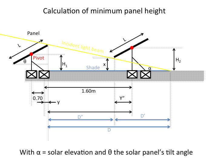
(morning and noon) when the sun's elevation angle is below 20° (see figures below, but rather that bothering with tedious, though not complicated, algebraic trigonometry, there is a better option to simulate shade using a free software SketchUp as shown here). To remedy this problem, one should have elevated the 2nd, 3rd and 4th row from the ground as depicted in the scheme below, in order to have the shadow passing bellow the panel's array of the line to its back .


Calculation of the panels height to avoid shading on the back row (system of individual panel arrays, not chosen due to the complexity related to elevating the panels from the ground and having a central pivot point)
 Finally a multiple array mount was chosen for its simplicity, though only mounts holding a maximum of 3 panels lines could be manufactured by our supplier, meaning that the first row would lie on an individual mount at ground level, spaced 2.10 m from the 3 panels lines mount. The shadow produced by the first row only affects the second row (the first row of the 3 panel mount), and only early in the morning and late in the afternoon the shortest days of winter (for roughly a month, from mid December to mid January). The loss on power generation is therefore not very significant, since at the time of shadowing the power generation is low.

Lateral view of the two mounts arrays adjusted to their autumn-spring angular position (34°). The individual mounts were connected together with twined copper wire (approx. 7 mm diameter each) and connected to the ground through a 1.5m copper coated steel rod to protect the system against lightnings.


Advantages and usage of DC source in off-grid photovoltaics

In my previous post I mentioned the advantages of a DC PV system. I will go through them in detail to clarify my point. Fist of all I should mention the typical voltage of the DC source we are working with is in the range of 300 to 350V, the value not being precisely fixed (in practice it can vary from 250V to 400V). This is to match approximately the maximum voltage point of the sinusoidal signal of the mains power supply in European countries, as to be able to adapt commercial appliances (made for AC230V) to DC. Such DC voltage is easily achieved connecting the adequate number of solar panels in series (e.g 7 x 48V; 10 x 36 V; 14 x 24V)
Maximum voltage point of an RMS ACV230 sine signal.


 1) A cheaper alternative to photovoltaic installations

This claim is supported by mainly two arguments. The first and most obvious one is that if DC generated by the PV array is directly used to power appliances we remove the need of a costly pure sine inverter. This is even a stronger argument when considering off-grid systems since they typically are in the 5-10 kW range and the price of a durable inverter-charger for such power typically exceeds 2000€. The second argument lies on the fact that with a DC system, energy consumption can be better optimized in such a way as to use energy when it is available, and store it in various different forms allowing downsizing the batteries (this point is developed bellow).
In practice many but not all the appliances can be modified to work on DC, so it is more convenient to install a mixed DC/AC system. In this latter case a pure sine wave inverter will still be needed, however its power output can be scaled down (and so its price) compared to a conventional system since most of the energy demanding work will be performed out of the DC. The AC will be used to power household appliances such as washing machines, dish washers, fridges, induction cooker... or any other appliances not fit for DC (or at least no easily modified to run on DC).

2) A more efficient way to use energy, using it when it is available, and storing it into different forms (electricity, heat, cold, potential energy).

This sounds pretty obvious! doesn't it? Well at low enough latitudes (typically those of the Mediterranean countries in Europe) there are sufficient sunshine days in a row not to be dependent on electricity storage except for illumination and nighttime.  Therefore there is no need for expensive deep cycle high capacity batteries.  All the energy demanding tasks are better carried out in day time and better carried out from the DC source directly as to adjust consumption with available energy, as for example:

-Running 3 phase motors from variable frequency drives allows varying the frequency (and thus the RPMs of the motor) as to adjust it to the available energy (e.g. on a sunny day full speed, on a cloudy day reduced speed)
- Heating up water, feeding the resistance of the boiler with a chopped voltage from the DC source, varying automatically the duty cycle to adapt the current consumption to the available energy (e.g. on a sunny day the water will heat up at a fast rate, while it may take several hours on a cloudy day, though still be warm at the end of the day)
- Controlling cold rooms or walk-in fridges (e.g. in a farm) with a variable frequency drive, adjusting the cooling rate with the available energy.
- Controlling the AC inverter current input and battery charging with a modified high power switched mode power supply, as to adjust it to the available energy.

3)  Automatize consumption

All the above tasks can be carried out in an automated manner. The simplest way to proceed is to modify the appliances in order to have them turning on/off according the DC voltage of the system (we call it the DC BUS) . That is the voltage of the PV array (or the BUS) evolves according to the solar irradiation and the load. The greater the load, the lower it goes following the I-V curve of the array (see figure). therefore, as long as the DC BUS is higher than VMPP, energy is available to use, appliances can then be given priority by setting their turn-on voltage to a higher or lower voltage. The current consumption of the appliance can then be adjusted (as explained above) to maintain the DC BUS to a desired value (in case current is drawn from another point on the BUS, or cloudy weather).
I-V curve of a hypothetical array of solar panel. The voltage of the BUS decreases with load "going up" the I-V curve.The evolution of the value of the BUS at a given solar incident light is proportional to the load. The operation of the appliances is performed according to the turn on threshold with a priority set for each appliance (the lower the threshold, the stronger priority).
For more precise appliances operation, maximum powerpoint trackers can be implemented to the equipement to accurately ajust the load to the available power at a given time.


Tuesday 21 April 2015

Direct current (DC) for off-grid photovoltaics?  

A little historical reminder of the current standards

More than a century has passed since the end of the war of current. But what was it all about? And why did alternate (AC) won over direct current (DC) generation?  Well simply put, it was just about current production and distribution! For more info on this check out the Wikepedia page here. Well it makes perfect sense that AC currents won, given that at the time of Thomas Edison and Nikola Tesla solid state electronics did not exist and that power generation from sustainable (local) sources wasn't at all considered an important criteria! Indeed,  DC current distribution implied that, to avoid losses in transmission through the wires, current should have been generated in close proximity of the consumers households since there was no convenient method to elevate the tension for long distances current transport, and subsequently lower the tension at the point where it were to be consumed. AC current was much better suited to the latter task using power transformers, which had been developed at the end of the nineteenth century (remember Maxwell-Faraday low of induction, transformer can only work with an alternating current). Then AC won and household appliances were developed specifically to function on AC current standards (mainly 2 standards ACV110 and ACV230) (Check this video from the "Post Apocalyptic Inventor" for a very good explanation on current generation and transport and transformers; I strongly recommend you check his Youtube channel if you are interested in electricity related subject).
Since the times of Edison and Tesla things have evolved quite a bit, especially in the area of power electronics, which at that time did not exist. With the invention of power transistors (and especially MOSFETs and IGBTs) lowering a DC voltage source has become much easier. The principle still relies on feeding an alternate source to the primary winding of a transformer, except that now the alternate current is fabricated by chopping a DC voltage source at a given frequency using a power transistor. This principle, most commonly known as  "inverter" is used nowadays in virtually all domestic appliances power supplies (so-called "switched mode power supplies", see here for an outstanding tutorial video series) which supplanted the old fashion primary transformer based power supplies. In other words, instead of using the properties of the 50/60Hz AC mains supply to reduce the voltage in our house hold appliances, the AC input is actually rectified to a positive DC voltage internally and subsequently chopped by means of a power transistor at a higher frequency (typically a few tenth of KHz) and fed through a transformer out of which the voltage comes out reduced to a given value. This method has many advantages, the first one being the extremely high achievable transformation yields (>90%), the very significant reduction of the transformer size (and therefore inducing a reduction in weight), and the ease of output voltage control.There are many other appliances which work on a similar principle, like variable frequency drives, air conditioners, welders....
So I'm getting to the point: One may ask himself, why would we question a current standard which has been established more than century ago? Taken out of context, there is no real motivation for that, but in the case of photovoltaic solar cells, where the current generated is DC type, and that power is generated in close proximity to where it is being consumed, there is a clear advantage if the current could be used straight out of the solar panels, rather than having to feed it to an expensive sine wave inverter which converts the DC output from the solar panels to a usable AC power source. In the following blog we describe the development of an off-grid photovoltaic system which takes advantage of DC power generation to provide for:

-A cheaper alternative to photovoltaic installations
-A more efficient way to use energy, using it when it is available, and storing it into different forms (electricity, heat, cold, potential energy).
-Automatize consumption according to the DC voltage output.